Vacuum, mechanical locating, clamping or magnetic forces are used to hold substrates on the chucks. Stainless steel, hard anodized aluminum, and various types of plastic chucks are available to suit different process requirements.
LS Vacuum Chucks - O-Ring
These vacuum chucks are designed to be used on HRI spinners equipped with 1/2 horsepower (BD) motor assemblies. The o-ring surface holds glass, quartz, ceramic and metal substrates. O-ring chucks seal to the substrate better than flat surface chucks, and give greater resistance to torque slippage. Typically O-ring chucks are not recommended for thin fragile substrates, such as silicon wafers. The O-ring seal projects above the chuck surface and the powerful vacuum will pull the substrate inside the O-ring area with sufficient force to significantly deform the substrate, and perhaps break it if it is brittle or has flaws around the edge. Flat surface chucks should be used for such substrates.
The substrate should overhang the chuck by 1/4" or more, to prevent fluid reaching the surface of the chuck. If fluid reaches the substrate/chuck interface, capillary forces will wick the fluid between the substrate and chuck, thereby fouling the backside of the substrate and the surface of the chuck. The o-ring chucks are typically provided with a plastic disc mounted below the surface of the chuck, with a larger diameter than the substrate. This disc provides a visual alignment aid to help center the substrate on the chuck. The disc also helps protect the backside overhang of the substrate from aerosol particle contamination during the spinning operation. Some o-ring chucks are designed as "raised center" chucks, meaning the alignment disc is a machined part of the chuck.
The recommended vacuum is 23 "/Hg or more. HRI spinner interlocks are typically set at the factory to operate at about 17 "/Hg, and drop out approximately 1-1/2 "/Hg below the operate point. 23"/Hg or more provides for quickly passing through the operate point, and therefore provides a quick consistent response. The interlock set-point is adjustable, and can be adjusted to a much lower level if necessary, for thin fragile substrates. An accessory vacuum regulator may be required to operate at a consistent vacuum, lower than the source.
The chart below lists some of the LS O-Ring Vacuum Chucks that have been designed. Please contact us if you do not find a chuck listed on this chart that meets your specifications. We can custom design chucks upon request.
| LS Type O-Ring Vacuum Chucks | ||
|---|---|---|
| O.D. Size | Hard Anodized Aluminum | Stainless Steel |
| 1/2"" | 2-24043 | |
| 2-3/4" | 2-15592 | |
| 3" | 2-23344 | |
| 3-1/2" with P-Hub | 2-21918 | |
| 4-3/4" | 3-18709 | |
| 5-1/2" | 2-22427 | |
| 5.7" with P-Hub | 3-21175 | |
| 6" | 3-21448 | |
| 7-3/4" | 3-14460 | |
| 8-1/2" | 1-10568 | |
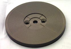
LS Vacuum Chucks
Mechanical Locating O-Ring
These vacuum chucks are designed to be used on HRI spinners equipped with 1/2 horsepower (BD) motor assemblies. The O-ring chuck is used with strong substrates such as glass masks, ceramic substrates, and metal substrates. The O-ring to substrate seal provides maximum holding power and the greatest resistance to slipping due to acceleration.
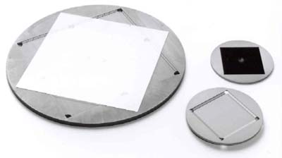
Four mechanical locating fingers, 90 degrees apart, provide locating guides for a square, rectangular or round substrate. The guide fingers are attached to the underside of the chuck and are adjustable in pairs. The ends of the alignment fingers bend upward and come above the surface of the chuck. If a substrate is improperly, i.e. sitting on one of the fingers, it will prevent a vacuum seal triggering the vacuum interlock systems. The vacuum interlock system will not permit a spin cycle to begin until there is sufficient vacuum. If using fragile substrates that could be deformed or broken by the vacuum power of the o-ring chuck please see our Flat Surface Mechanical Chuck designs.
If the fingers project above the surface of the substrate then air turbulence can cause local, non-uniformity of the coating film near each finger. Also, if fluid reaches the substrate/chuck interface capillary forces will wick the fluid between the substrate and chuck, thereby fouling the backside of the substrate and the surface of the chuck. If better film uniformity and backside protection is necessary, please see our Recess Type Chuck designs.
The recommended vacuum is 23 "/Hg or more. HRI spinner interlocks are typically set at the factory to operate at about 17 "/Hg, and drop out approximately 1-1/2 "/Hg below the operate point. 23"/Hg or more provides for quickly passing through the operate point, and therefore provides a quick consistent response. The interlock set-point is adjustable, and can be adjusted to a much lower level if necessary, for thin fragile substrates. An accessory vacuum regulator may be required to operate at a consistent vacuum, lower than the source.
The chart below lists some of the LS Mechanical Locating O-Ring Vacuum Chucks that have been designed. Please call us if you do not find a chuck listed on this chart that meets your specifications. We can custom design chucks upon request.
| LS Type Mechanical Locating O-Ring Vacuum Chuck Material - Hard Anodized Aluminum |
|
|---|---|
| Substrate Size (Finger Extensions) | HRI Part Number |
| 4-1/4" to 6" | 2-23033 |
| 6" to 8" | 1-15226 |
| 11" to 13" | 3-22782 |
| 12" to 18" | 1-24163 |
| 15" X 15" (non-adjustable finger extensions) | 3-23214 |
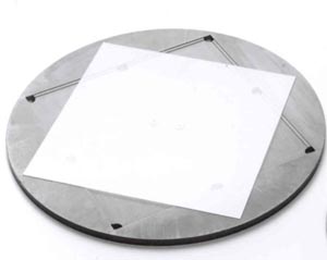
LS Vacuum Chucks
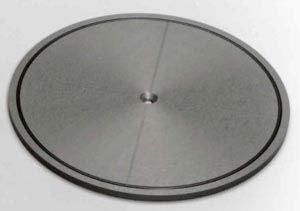
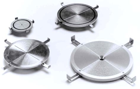
Flat Surface Cross & Scroll
These vacuum chucks are designed to be used on HRI spinners equipped with 1/2 horsepower (BD) motor assemblies. The flat surface chucks hold thin, flat substrates such as silicon, glass or germanium. The scroll design on the top surface of the chuck aids in the distribution of vacuum. The LS Type Flat Surface Vacuum Chuck can also be used with our Substrate Lifter/Alignment Assembly. When used with this assembly, the chuck is sold with a Lifter Rod that lifts the wafer out of the bowl area. An Alignment Plate, which is part of the Substrate Lifter/Alignment Assembly, is then used to align the wafer. The perfectly centered wafer, rests on the Lifter Rod Platform and is lowered onto the vacuum chuck. Please see the LS-Lifter Rod chart below.
The substrate should overhang the chuck by 1/4" or more, to prevent fluid reaching the surface of the chuck. If fluid reaches the substrate/chuck interface, capillary forces will wick the fluid between the substrate and chuck, thereby fouling the backside of the substrate and the surface of the chuck. The flat-surface chucks are typically provided with a plastic disc mounted below the surface of the chuck, with a larger diameter than the substrate. This disc provides a visual alignment aid to help center the substrate on the chuck. The disc also helps protect the backside overhang of the substrate from aerosol particle contamination during the spinning operation. Some flat surface chucks are designed as "raised center" chucks, meaning the alignment disc is a machined part of the chuck.
The recommended vacuum is 23 "/Hg or more. HRI spinner interlocks are typically set at the factory to operate at about 17 "/Hg, and drop out approximately 1-1/2 "/Hg below the operate point. 23"/Hg or more provides for quickly passing through the operate point, and therefore provides a quick consistent response. The interlock set-point is adjustable, and can be adjusted to a much lower level if necessary, for thin fragile substrates. An accessory vacuum regulator may be required to operate at a consistent vacuum, lower than the source.
The chart below lists some of the LS Flat Surface Vacuum Chucks that have been designed. Please call us if you do not find a chuck listed on this chart that meets your specifications. We can custom design chucks upon request.
| LS Type Flat Surface Cross & Scroll | |||
|---|---|---|---|
| O.D. Size | Hard Anodized Aluminum | Acetal | Stainless Steel |
| 3-5/16" | 2-23120 | 2-22879 | 2-22877 |
| 4-1/2" | 2-23342 | ||
| 5-1/2" | 2-22425 | ||
| 8" | 2-21232 | ||
 LS Type Flat Surface Cross & Scroll LS Type Flat Surface Cross & ScrollDesigned to be used with a Substrate Lifter Assembly Lifter Rod to lift the wafer from the chuck surface is supplied w/each chuck |
|
|---|---|
| O.D. Size - Hard Anodized Aluminum | HRI Part Number |
| 2-3/4" | 2-24030 |
| 3-1/2" | 2-22916 |
| 5-1/2" | 2-24028 |
| 7-1/4" | 2-23038 |
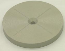
LS Non-Vacuum Chucks - Carrier/Recess
These vacuum chucks are designed to be used on HRI spinners equipped with 1/2 horsepower (BD) motor assemblies. The recess chucks are machined to customer specification.
The substrate is held in a pocket that closely conforms to the substrate's dimensions. The top surface of the substrate is essentially level with the top surface of the chuck, thus giving the appearance (from a coating point of view) of a circular substrate. No vacuum is used to hold the substrate, however, slots that extend from the backside of the chuck to the cavity beneath the substrate induce a negative cavity pressure while spinning, which holds the substrate in place. These slots also provide drainage for any fluids that enter the cavity around the edges of the substrates. An o-ring vacuum sub-chuck secures the recess carrier to the rotating spindle. Since the sub-chuck can accommodate various sizes of recess carrier chucks, the user can easily switch between different sizes of substrates.
The chart below lists some of the LS Non-Vacuum Carrier/Recess Chucks that have been designed. Please call us if you do not find a chuck listed on this chart that meets your specifications. We can custom design chucks upon request.
| LS Non-Vacuum Carrier/Recess Chuck | ||
|---|---|---|
| Substrate Size | Hard Anodized Aluminum Base HRI Part Number |
Base Chuck Size |
| 4" x 4" | 3-18709 | 4-3/4" O-Ring |
| 5" x 5" | 3-18709 | 4-3/4" O-Ring |
| 6" x 6" | 3-18709 | 4-3/4" O-Ring |
| 8" x 10" | 3-14460 | 7-3/4" O-Ring |
| 12" x 12" | 3-14460 | 7-3/4" O-Ring |
| 14" x 14" | 3-14460 | 7-3/4" O-Ring |
| 12" x 13" | 3-14460 | 7-3/4" O-Ring |
| Non-Vacuum Recess Chucks are machined to customer's substrate dimensions and tolerances | ||
LS Type Non-Vacuum Recess Chucks
These vacuum chucks are designed to be used on HRI spinners equipped with 1/2 horsepower (BD) motor assemblies. The recess chucks are machined to customer specifications.
The substrate is held in a pocket that closely conforms to the substrate's dimensions. The top surface of the substrate is essentially level with the top surface of the chuck, thus giving the appearance (from a coating point of view) of a circular substrate. No vacuum is used to hold the substrate, however, slots that extend from the backside of the chuck to the cavity beneath the substrate induce a negative cavity pressure while spinning, which holds the substrate in place. These slots also provide drainage for any fluids that enter the cavity around the edges of the substrates.
The chart below lists some of the LS Non-Vacuum Recess Chucks that have been designed. Please call us if you do not find a chuck listed on this chart that meets your specifications. We can custom design chucks upon request.
| LS Type Non-Vacuum Recess Chuck | ||
|---|---|---|
| Substrate Size - Hard Anodized Aluminum | HRI Part Number | |
| 2" x 2" | CUSTOM | |
| 2" x 3" | CUSTOM | |
| 4" x 4" | CUSTOM | |
| 5" x 5" | CUSTOM | |
| 6" x 6" | CUSTOM | |
| 10" x 10" | CUSTOM | |
| 12" x 12" | CUSTOM | |
| Non-Vacuum Recess Chucks are machined to customer's substrate dimensions and tolerances | ||
Select Below for Information on All Chucks